After learning some basic knowledge about Arduino Uno and Board and Arduino programming, the more challenging tasks was given to me which were to interface some components to create input devices and output devices. My Arduino programming journey:
Work
on Input Devices
1. a. My first task is to interface a Potentiometer Analog Input to maker UNO
board and measure its signal in serial monitor Arduino IDE.
Step:
1. Access the Tinkercard website to create my own virtual circuit.
2. At the right panel, drag a breadboard and an Arduino Board onto the workplane.
3. Then, Drag
a resistor, LED and Potentiometer onto the workplane from the components panel.
3. Select the resistor and set the resistance as 220 ohms.
4. Connect all the components with the breadboard and Arduino Uno board as below.
5. After that, open the code editor by clicking the button labelled "code" at the right top panel.
6. Code with blocks:
(i) Select the grey notation block and drag out the comment block.
(ii) Then, type read the value from the sensor.
(iii) Click on the pink variables category and drag out a "set" block to the right empty section.
(iv) Set the variable named sensorValue to "read analog pin A0" (created from the Input category).
(v) Select the output category and drag out a first blue block to set the built-in LED as HIGH.
(vi) Click the control category and drag out a wait block.
(vii) Change the 1 to sensorValue and set it as milliseconds.
(vii) Repeat the (v) step by changing the built-in LED as LOW and then repeat again (vi) and (vii) steps.
7. After finishing the code with blocks, click the menu on the left and select the blocks+test section. Arduino code will be generated by the code block.
8. Click on the start simulation button and try to adjust the potentiometer. By adjusting it anticlockwise gradually, the flashing rate of LED light will increase.
9. Connect all the components with the physical Arduino Uno Board by following the virtual circuit sketch.
10. After that, connect the Uno board to the laptop by plugging in the USB cable.
11. Copy the code and then open the Arduino IDE app. Then, paste that code into an empty Arduino sketch. Click the verify icon and then the upload icon.
12. Lastly, I try to turn the knob to adjust the flashing rate of the LED light. In the meantime, I click on the serial motor icon at the right top corner. I can observe the displayed number on the serial motor screen changing when I'm turning the knob.
b. Interface an LDR to maker UNO board and measure its signal
in serial monitor Arduino IDE.
Step:
1. Access the Tinkercard website to create a new circuit.
2. At the right panel, drag a breadboard and an Arduino Board onto the workplane.
3. Then, drag 2 resistors, an LED and an LDR onto the workplane from the components panel.
3. Select the resistor and set the resistance as 220 ohms. It applies to another resistor.
4. Connect all the components with the breadboard and Arduino Uno board as below.
5. After that, open the code editor by clicking the button labelled "code" at the right top panel.
6. Code with blocks:
(i) Click on the pink variables category and drag out a "set" block to the right empty section.
(ii) Set the variable named photoresistor to "read analog pin A0" (created from the Input category).
(iii) Select the output category and drag out print to serial monitor block. Drag the variable named photoresistor to substitute hello world naming and select "with" newline.
(vi) Drag out set pin block from Output category to set the pin as 11. Then drag the map block from the math category and put it into the same pin block beside the "to". In the map block, set the variable named photoresistor and then set the range from 0 to 225.
(vii) Click the control category and drag out a wait block.
(vii) Change the 1 to 10000 and set it as milliseconds.
7. After finishing the code with blocks, click the menu on the left and select the blocks+test section. Arduino code will be generated by the code block.
8. Click on the start simulation button and then select the LDR to adjust the brightness. Observe the brightness of the LED light.
9. Connect all the components with the physical Arduino Uno Board by following the virtual circuit sketch.
10. After that, connect the Uno board to the laptop by plugging in the USB cable.
11. Copy the code and then open the Arduino IDE app. Then, paste that code into an empty Arduino sketch. Click the verify icon and then the upload icon.
12. Lastly, I try to cover the LDR with my thumb to see the changes in the brightness of the LED light. In the meantime, I click on the serial motor icon at the right top corner. I can observe the displayed number on the serial motor screen changing when I cover the LDR.
a. Interface 3 LEDs (Red, Yellow, Green) to maker UNO board
and program it to perform fading.
Step:
1. Access the Tinkercard website to create a new circuit.
2. At the right panel, drag a breadboard and an Arduino Board onto the workplane.
3. Then, drag 3 resistors and 3 LEDs (Red, Yellow, Green) onto the workplane from the components panel.
3. Select the resistor and set the resistance as 220 ohms. It applies to all resistors.
4. Connect all the components with the breadboard and Arduino Uno board as below.
5. After that, open the code editor by clicking the button labelled "code" at the right top panel.
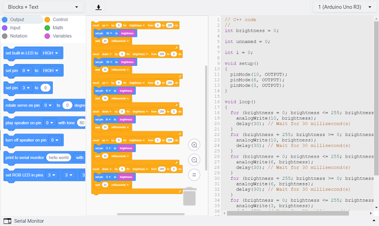
6. Code with blocks:
(i) Select the control category and drag out the count block. Select "up", by "5" and for "brightness". Set the range of do from 0 to 255.
(ii) Then, drag out the set pin block from the output category. Set the pin as 10 and set the variable named brightness (create from variables category).
(iii) Click the control category and drag out a wait block. Set as 30 milliseconds.
(iv) Drag out the count block again. Select "down", by "5" and for " brightness. Set the range of do from 0 to 225.
(v) Repeat (ii) and (iii).
(vi) Repeat step (i) to (v) by changing the pin number with 6 and 9.
(vii) Join all the blocks together.
7. After finishing the code with blocks, click the menu on the left and select the blocks+test section. Arduino code will be generated by the code block.
8. Click on the start simulation button and observe the brightness of the LED light. The 3 LED lights will fade one after another.
9. Connect all the components with the physical Arduino Uno Board by following the virtual circuit sketch.
10. After that, connect the Uno board to the laptop by plugging in the USB cable.
11. Copy the code and then open the Arduino IDE app. Then, paste that code into an empty Arduino sketch. Click the verify icon and then the upload icon.
12. I can observe the 3 LED lights fade one after another.
b. Interface the DC motor to maker UNO board and program it
to on and off using push button on the board
Step:
1. Access the Tinkercard website to create a new circuit.
2. At the right panel, drag a breadboard and an Arduino Board onto the workplane.
3. Then, drag a resistor, a pushbutton and a dc motoronto the workplane from the components panel.
3. Select the resistor and set the resistance as 220 ohms.
4. Connect all the components with the breadboard and Arduino Uno board as below.
5. Next, open the code editor by clicking the button labelled "code" at the right top panel.
6. For this case, I didn't use the code with blocks method. I copy the DigitalInputpullup code example from the Arduino IDE app.
7. After that, select the start simulation button. Click on the push button and continue clicking on it. The rpm of the dc motor will increase speedily to 5000rpm. Once I release the push button, the rpm of the dc motor will drop to 0.
In this individual work, I had enhanced my understanding of Arduino programming. I felt it was fun when doing this task even I had encountered some difficulties during the process. I was able to complete the first 3 sections of this task but except for the last part. I failed to interface the dc motor to my physical Arduino Board and
program it on and off using the push button on the board. The sketch I created in Tinkercad is for Arduino Uno R3 with no programmable button inside the board. However, the Arduino Board I used is included a programmable button inside the board. Hence, when I connected the dc motor with the board in real life, the connection for the pushbutton is not necessary. Then, after uploading the code to the board, the process did not work. The dc motor did not operate when I turned on the programmable button. It meant that my code was incorrect to program the on and off button on the board. I tried to research online and tried to edit the code but the still failed to solve the problem. The other possible way to solve this problem was to use a pushbutton component and connect it as my sketch in Tinkercad instead of using the button on the board. But I am not provided with this component so I will buy it online or in the shop to try this solution in the future. Anyways, I found this task will benefit me when doing the Arduino programming for my tea-maker project.


No comments:
Post a Comment