Computer-Aided Design Part 1
Creating a Key Chain in
Fusion360
This CAD task is to create our
own key chain in Fusion360. Let’s move on to the steps on how to make my
personalized key chain.
1. First, I click create sketch icon and select a construction plane.

2. Next, choose 2-point rectangle to draw a 65×25mm rectangle.

3. Then, press Fn+o to create a 2mm offset.

4. On the Sketch contextual tab,
select Fillet icon. After that, click on the 4 outer corners of the rectangle to create fillets. It will appear a radius manipulator and specify as
5.0mm.

5. Select line icon. Draw a line at the front part of the rectangle. Refer to the diagram below. After drawing it, select that line and right-click my mouse and then click normal/construction selection.

6. Select the 'dimension' icon and click on line 1 and line 2 to
define a 7mm between them.

7. Under create, select point selection. Then, create a draw point in the middle of line 2.

8. Draw a 5mm circle from the
point that was recently created.

9. Now, it’s time to create my name. Select Text icon and then I type Zhi Wei.


11. In order to be continued the next step, I have to hide all
bodies from the browser and show my sketch. After that, select my name and the
border to extrude as 1.5mm. From the extrude menu, select offset plane and
enter 3mm.

12. Finally, I click on the “eye” icon of bodies and hide the sketches. My own key chain is done!

Reflection
This activity is basically to help us recall what we have learned about Fusion360 last semester. Our memories about Computer-Aided Design basic skills will be refreshed and consolidated during this task. In this refresher activity, I realized that I almost forgot how to use Fusion360. Fortunately, with the video guideline, I am able to create my own key chain sketches and be more familiar with how to use Fusion360. This activity will help me build a basement of this skill before proceeding to CAD Part 2.Computer-Aided Design Part 2
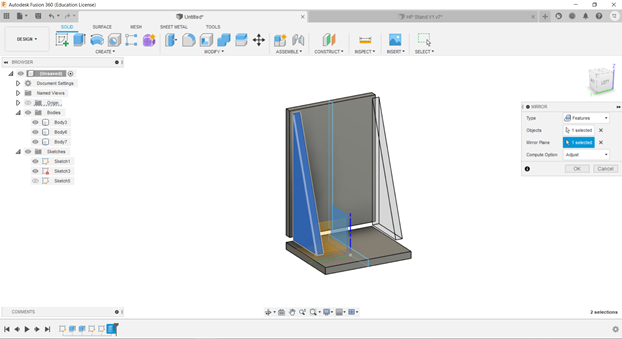
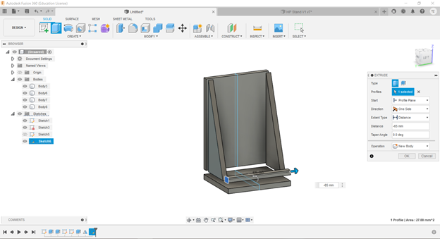
A more interesting CAD task is given in week 2. We have to design a simple handphone stand our own that can be made by laser cutting. After doing some research and brainstorming, I have an idea of how to design my handphone stand. Below will show my design journey of handphone stand in Fusion360.
1. To start, I select the 'rectangle' icon and draw 2 rectangles like L shape as the dimension of 5x90mm and 5x55mm as in the diagram below. After that, I select the 'finish sketch' (green tick icon).

2. Under Modify, I click the 'Change Parameter' icon. After that, it will display a parameters dialog. I set up thickness at 5mm, height at 90mm and width at 55mm. Once I set up certain parameters, it will automatically add them to my favourite parameters. Hence, when I am typing the name of my favourite parameters in any compatible value field, my favourite parameters display as suggestions so that I can easily reuse them through a design. In addition, my design sketch will reflect changes once I edit and update the parameters.


No comments:
Post a Comment